
A camera-based inspection line can look simple: a lens above a conveyor, a light, and a reject gate. Yet a reflective metal surface, a blurred label, or a shift in product position can change what the system detects. Buyers comparing the 2026 market need more than resolution figures. They need evidence that the system works with their actual parts, line speed, lighting, and acceptable defect limits.
The International Federation of Robotics’ World Robotics 2024 report recorded 541,302 industrial robot installations worldwide in 2023, bringing the operating stock to about 4.28 million. That growth makes automated inspection increasingly relevant, but robot figures do not prove that any particular camera system will perform well. IFR President Marina Bill noted, “The number of industrial robots operating in factories around the world has reached a new record of about 4.3 million units.” It is a useful signal of automation’s scale, not a substitute for a factory trial.
This guide compares leading Camera Based Inspection System options through practical buyer criteria: image consistency, inspection speed, integration effort, traceability, and support. Ask vendors to test difficult samples, including glare-prone parts and subtle defects. Small details matter. A polished demo may not represent a full shift. Buyers should also check how performance is measured and what happens when the product or process changes. No system is perfect. The right choice is the one whose limits are visible, measurable, and manageable.
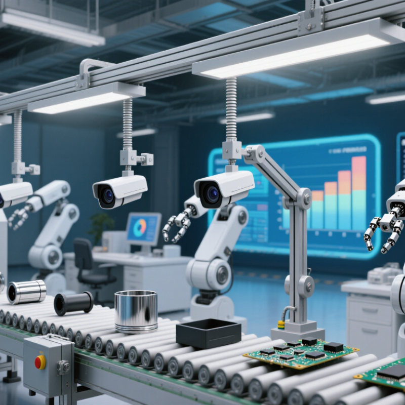
Camera-based inspection systems use images to check products, parts, or packaging against defined quality criteria. A typical setup combines an industrial camera, lens, controlled lighting, image-processing software, and a signal to a production-line controller. The camera captures an image when a sensor or encoder marks the right moment. Software then checks features such as dimensions, surface marks, missing components, or print alignment. The system can flag a suspect item for review or removal.
Lighting matters. A glossy surface can hide scratches under one angle and reveal them under another.
Performance depends on more than camera resolution. Exposure, motion blur, lens choice, product variation, and the quality of example images all affect results. Bergmann and colleagues’ 2019 CVPR anomaly-detection benchmark reported 5,354 high-resolution images across 15 object and texture categories, illustrating the range of visual conditions inspection models may need to handle.
That benchmark is useful context, not a guarantee of factory performance. A clean laboratory image is not a moving production line. Teams should test with real parts, including ordinary variation and borderline defects.
This step is sometimes underestimated. Even a capable system can miss defects that were poorly lit or absent from its training examples.
A camera-based inspection system is more than a camera pointed at a product. It combines optics, lighting, image sensors, processing hardware, and software. Each part affects what the system can detect. A lens must capture the smallest defect at the required working distance. A sensor needs enough resolution and speed for the production line. More pixels alone do not guarantee better results.
Lighting matters. A matte surface may need broad, even illumination, while scratches on metal can become clearer under angled light. Backlighting can reveal missing holes or irregular outlines. In practice, a small change in product position may alter the image, so mounting and fixturing deserve careful testing. It is easy to overlook this.
Inspection technology should match the defect. Rule-based vision can measure dimensions, locate edges, and check presence when conditions stay consistent. Machine-learning vision can help classify variable surface defects, but it needs representative images and ongoing review. Neither approach fixes poor image quality. Buyers should test real samples, including acceptable parts and difficult borderline cases, then track false rejects and missed defects. Results can vary. A well-documented trial is more useful than a polished demonstration alone.
A useful comparison begins with the defects the system must detect, not the camera’s headline resolution. Check whether it can reveal the actual flaw, such as a hairline crack beside a reflective edge or a missing component in a crowded tray. Lighting changes everything. Ask suppliers to test representative parts under the same conditions, including surface finish, product position, and line speed. A clear image in a demo may not translate to stable results on a moving production line.
Measure repeatability, false rejects, and missed defects across multiple runs. Request results with sample size and test conditions, not just a single accuracy figure. That matters. Also compare field of view, exposure time, calibration effort, and how inspection results reach operators or existing production software. A system that spots defects but slows the line may create a different problem.
Specifications can hide setup work. Allow time to test real parts, especially awkward colors, glare, and normal variation between batches. I would be cautious about relying on one perfect sample; it can make performance look better than it is. Record how often settings need adjustment and whether operators can understand an alert quickly. Those details are easy to overlook, and they deserve a place in the buying comparison.
Camera-based inspection works best when matched to a specific defect and production step. On an electronics line, a camera may check connector pins under fixed lighting; on a packaging line, it may detect a crooked label or damaged seal. The International Federation of Robotics reported 541,302 industrial robot installations worldwide in 2023, in its World Robotics 2024 report. As inspection moves closer to automated handling, timing and communication matter as much as image resolution. Small details matter.
Buyers should confirm how cameras exchange inspection results with the PLC, reject mechanism, and quality records. Specify trigger timing, part presentation, lighting, image storage, and what happens when a result is uncertain. A fast camera cannot fix a part that arrives rotated or partly hidden. Real lines are messy. Test with actual parts, including scratched surfaces, glare, dust, and normal shifts in ambient light. Not every defect is repeatable, either; borderline images may need operator review. A useful acceptance test measures false rejects and missed defects across representative production runs, not just a handful of clean samples. Integration is rarely perfect on day one, and maintenance teams need a clear way to clean lenses, verify lighting, and recalibrate after a fixture change.
Industry applications and integration requirements: theoretical image-data throughput by GigE interface speed.
The bars show theoretical maximums calculated from interface line rate, assuming 8-bit monochrome pixels and decimal units (1 GB = 1,000 MB). Actual image payload throughput is lower because of protocol overhead and system constraints. Packaging and labeling, electronics, automotive, and pharmaceutical inspection systems should be sized for camera resolution, frame rate, number of cameras, host performance, and network capacity.
When evaluating camera-based inspection systems, begin with the defect you need to detect, not the headline camera resolution. A fine surface crack on a moving part may need different lighting and exposure settings than a missing component. Ask suppliers to test representative parts, including dull, reflective, dusty, and slightly misaligned examples. Bring known defects and acceptable variations. A polished demonstration is not enough. It can be a small, comforting sample.
Measure detection rates and false rejects under your actual line speed. Record results across repeated runs, shifts, and lighting changes. Check whether operators can review flagged images and adjust approved settings without specialist help. Also examine integration needs: available space, triggering signals, data storage, and maintenance access. Small details matter. A lens that is difficult to clean can quietly reduce performance. No test set is perfect, so document what was not tested and revisit those gaps before purchase. Compare the full operating cost, including setup, training, calibration, and downtime—not just the equipment price.
Compare common vision-system configurations by inspection task, output, and practical selection criteria. Capabilities depend on optics, lighting, motion, software, and the application.
| System option | Best suited to | Typical inspection output | Key advantages | Main limitations | What buyers should verify |
|---|---|---|---|---|---|
| 2D Area-Scan Vision | Stationary or indexed parts; labels, presence or absence, surface marks, dimensions, and assembly checks. | Two-dimensional images and measurements in the camera’s field of view. | Flexible setup for discrete parts; widely applicable; can capture a full scene in one exposure when the field of view and resolution permit. | Does not directly measure height or depth. Results can be affected by glare, shadows, low contrast, and part-position variation. | Confirm pixel resolution at the actual field of view, lens working distance, exposure time, lighting arrangement, and performance on representative samples. |
| 2D Line-Scan Vision | Continuous materials or moving products, such as web, sheet, paper, film, textiles, and conveyed surfaces. | Continuous two-dimensional images assembled from successive scan lines as the material moves. | Can inspect long or wide moving surfaces; image length is not limited to a single area-camera frame. | Requires synchronized motion and scanning. Speed variation, vibration, or poor encoder setup can distort images. | Check line rate against line speed, encoder synchronization, cross-web resolution, illumination uniformity, and data-processing capacity. |
| 3D Laser-Triangulation Profiling | Moving parts or surfaces where height, profile, edge position, or cross-sectional shape matters. | Height profiles; multiple profiles can be combined into a 3D surface representation. | Measures surface geometry rather than relying only on brightness differences; useful for steps, gaps, warpage, and profile checks. | Performance can be affected by highly reflective, transparent, dark, or steep surfaces, depending on the sensor and setup. | Validate height repeatability, lateral resolution, scan speed, sensor angle, surface compatibility, and calibration method. |
| Structured-Light 3D Imaging | Stationary or briefly presented objects requiring a broader 3D shape or surface capture. | A 3D point cloud or surface map calculated from projected patterns and camera images. | Captures surface shape over an area; can support dimensional checks on complex objects without contact. | Movement during capture can introduce artifacts. Occlusions and reflective or transparent surfaces may reduce usable data. | Assess capture time, working volume, point spacing, occlusion handling, surface finish, and required measurement uncertainty. |
| Multispectral or Hyperspectral Imaging | Applications where material or chemical differences are not reliably distinguishable in ordinary color or grayscale images. | Images across selected wavelength bands or many contiguous spectral bands, depending on the system. | Can reveal spectral differences that standard visible-light imaging may not show; useful for selected sorting and material-inspection tasks. | Often involves more complex calibration, lighting, data handling, and application-specific analysis than conventional imaging. | Test whether the target materials have measurable spectral separation; confirm illumination, scan speed, calibration, and analysis requirements. |
"*" indicates required fields