What Is a CCS Busbar and How Does It Work?
A CCS Busbar, or cell contact system busbar, helps connect battery cells within a battery module. In electric vehicles, it can provide conductive paths between cells and support the collection of voltage or temperature signals. Its exact design depends on the battery’s layout, chemistry, and electrical requirements. The term can also be used differently across suppliers, so checking the product specification matters.
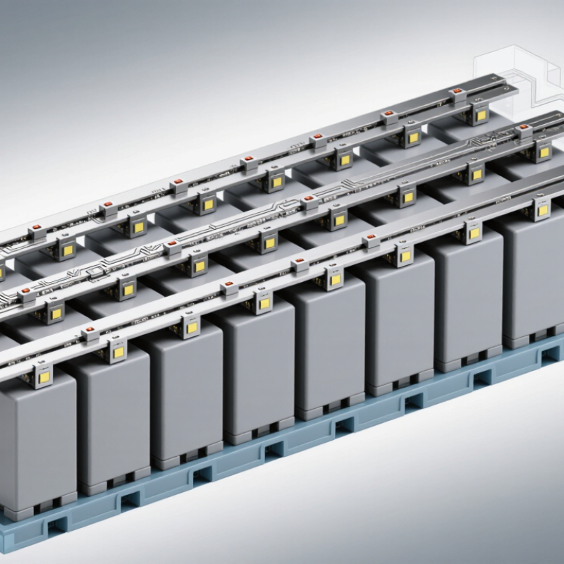
Picture a row of cells joined by thin metal conductors, held in a molded carrier. Some designs include flexible circuit elements, sensor connections, and insulating features. Together, these parts can reduce loose wiring and make assembly more organized. They do not remove the need for careful engineering. Clearances, contact quality, heat, vibration, and insulation all affect performance. Small details matter.
Understanding how a CCS Busbar works starts with its two main roles: carrying current and, where included, routing measurement signals. During operation, current flows through conductive sections between cells and other parts of the battery system. Signal paths can relay cell data to monitoring electronics, which help assess battery condition. The busbar itself does not manage the battery or guarantee safety. Those tasks depend on the wider system, including its controls, protection devices, and manufacturing quality.
This guide will examine the components, operating principles, materials, and design considerations behind CCS busbars. It will also distinguish common configurations and explain where trade-offs arise. One point is easy to overlook: a neat-looking assembly is not proof of reliable performance. Verification still matters.
What Does CCS Mean? Copper-Clad Steel Busbar Layers and Core Materials
CCS means copper-clad steel. A CCS busbar has a steel core covered by a continuous copper layer. The steel provides stiffness and tensile strength; the copper offers a more conductive surface. Together, these materials can create a bar that is stronger than copper alone, though its electrical performance depends on the copper thickness and core design.
The layers are bonded during manufacture, rather than simply stacked loosely. This bond helps the materials act as one piece when the bar is cut, drilled, or mounted. Look closely at a cross-section: copper should cover the steel consistently, including around edges. Exposed steel at a joint can corrode or create a poor electrical connection. Small details matter.
CCS is not electrically identical to solid copper. Its resistance and current capacity depend on dimensions, temperature, connection quality, and the specific copper-to-steel ratio. A thicker copper layer generally improves conductivity, while a larger steel core can add strength and reduce material cost. There is a trade-off. For a real installation, check measured specifications and joint requirements instead of relying on the material name alone. That caveat is easy to overlook.
What Is a CCS Busbar and How Does It Work? — What Does CCS Mean? Copper-Clad Steel Busbar Layers and Core Materials
| Dimension | Description | Role or Design Consideration |
| Meaning of CCS | CCS means copper-clad steel: a steel core covered by a bonded copper layer. | The composite combines the mechanical strength of steel with a conductive copper exterior. It is not solid copper. |
| Typical layer arrangement | From the outside inward: copper cladding, a bonded interface, and a steel core. | The copper layer is joined to the steel rather than acting as a loose sleeve. The bond helps the materials function as one conductor. |
| Copper cladding | The outer copper layer provides a conductive surface and helps protect the steel beneath it. | Cladding thickness and continuity affect electrical performance and corrosion protection. They should be specified for the intended application. |
| Steel core | The central steel material contributes strength and resistance to bending or mechanical loads. | Steel is less electrically conductive than copper, so a CCS busbar generally does not match a same-size solid-copper bar electrically. |
| How it carries current | Current flows through the conductive composite. In DC use, current distribution depends on the electrical properties and geometry of both bonded materials. | At AC, skin effect can influence current distribution toward the conductor’s surface; its significance depends on frequency, dimensions, and material properties. |
| Busbar function | A busbar provides a common conductive path to collect and distribute electrical power between equipment or circuit connections. | CCS can be considered where mechanical strength and material use matter, but electrical ratings must be established for the specific design. |
| Electrical rating | Allowable current depends on cross-sectional area, cladding thickness, temperature limits, cooling, installation conditions, and connection quality. | Do not determine ampacity from material name alone. Use verified design data and applicable electrical requirements. |
| Connections and joints | Terminations must provide a reliable electrical contact and accommodate the busbar’s material and surface construction. | Joint resistance, contact pressure, surface condition, and temperature rise can affect performance and should be checked in the finished assembly. |
| CCS versus solid copper | CCS has a steel core and copper exterior; solid copper is copper throughout its cross-section. | They are not automatically interchangeable. Compare conductivity, dimensions, temperature rise, mechanical loading, and connection requirements. |
Design note: CCS busbar properties vary with the steel grade, copper-cladding thickness, dimensions, and manufacturing process. Confirm material data and electrical ratings for the specific product and application.
How Is a CCS Busbar Made? Cladding, Bonding, and Cross-Section Design
A CCS busbar combines a steel core with a copper outer layer. The steel adds stiffness; the copper provides the main low-resistance current path. In production, surfaces are cleaned, aligned, and joined by roll bonding or another qualified cladding process. Heat and pressure must create a continuous interface, not just a tidy-looking seam. Small defects matter.
The Copper Development Association’s technical guide Copper for Busbars uses copper’s 100% IACS conductivity as a reference value. A CCS bar’s effective resistance depends on copper-layer thickness, steel grade, bonding quality, and temperature, so that reference is not a finished-product rating. Manufacturers should verify dimensions and bond integrity through suitable inspection and electrical testing. A neat drawing can still mislead.
Cross-section design balances current, temperature rise, mechanical strength, and available space. Wider bars offer more surface area for cooling; thicker steel can improve rigidity but adds weight and does not replace adequate copper area. Engineers also assess fault forces: IEC 60865-1 describes calculation methods for the mechanical effects of short-circuit currents. Rounded edges and consistent cladding thickness help control local heating. Details count. Real operating conditions may expose assumptions that a simple calculation misses.
How Does Current Flow Through CCS? Copper’s 58 MS/m IACS Benchmark at 20°C
What Is a CCS Busbar and How Does It Work?
In a CCS busbar, a copper layer is bonded to a steel core. The copper provides a low-resistance path, while the steel adds stiffness and strength. At a joint, current enters through the clamped contact area and spreads along the copper surface. Some current can also pass through the steel; the exact split depends on copper thickness, bonding, geometry, and temperature. The distinction matters.
At 20°C, 58 megasiemens per metre (MS/m) is the 100% IACS conductivity benchmark for annealed copper. IEC 60028 provides the reference standard, while ASTM B193 describes methods for measuring conductor-material resistivity. These figures describe reference copper, not every finished CCS bar. A thin copper layer, imperfect bond, or rough contact can increase resistance. Small details matter.
For example, a four-terminal resistance test can help distinguish the bar’s resistance from losses at its test connections. Under alternating current, current distribution also changes with frequency and conductor dimensions. So the copper benchmark alone cannot predict busbar temperature rise. Engineers still need to check dimensions, joints, load, and cooling. That assumption deserves a second look.
How Are CCS Busbar Ratings Determined? I²R Heating and IEC 61439 Temperature-Rise Limits
A CCS busbar’s current rating is a thermal limit, not just a measure of its cross-section. Losses follow I²R: a 1,000 A path with 10 μΩ resistance releases 10 W. That heat concentrates at joints, where contact pressure, surface condition, and fastener torque matter. The International Annealed Copper Standard sets 100% IACS conductivity at about 58 MS/m at 20°C. Copper resistance also rises roughly 0.39% per °C, so a hot bar produces more heat at the same current. Small changes matter. Ratings therefore depend on material, geometry, enclosure airflow, joint design, and ambient temperature—not amperage alone.
IEC 61439-1:2020, Table 6, sets temperature-rise limits by component and connection conditions; it does not give every busbar one universal allowable rise. External conductor terminals, for example, have a 70 K rise limit under the standard’s specified conditions, while busbar limits depend on nearby insulation, connected equipment, and contact materials. Assembly temperature-rise performance must be verified using the standard’s permitted design-verification methods. A sensible rating needs real enclosure and connection details, not a bare-bar calculation. Reality is less tidy. A loose joint or blocked vent can turn a compliant calculation into an overheated cabinet. The design record should state the test or assessment conditions, ambient temperature, and measurement points, so the rating can be checked against the installation.
Where Are CCS Busbars Used? Grounding, Fault-Current Paths, and Selection Factors
CCS (copper-clad steel) busbars are used in grounding and bonding assemblies where a conductive path must carry fault current toward protective equipment. In substations, switchgear, and industrial panels, they connect equipment frames, grounding conductors, and earth grids. During a fault, the path helps limit dangerous voltage differences and lets protection devices detect abnormal current. A real detail: a loose bolted joint can become a hot spot. The busbar alone cannot guarantee safety.
Selection starts with the prospective fault current and the time protection takes to clear it. IEC 60909-0:2016 provides methods for calculating short-circuit currents; IEEE Std 80-2013 assesses grounding safety using touch and step voltages, fault duration, and 50 kg and 70 kg body-weight assumptions. Those figures matter. Check the bar’s cross-section, copper-cladding integrity, joint hardware, corrosion exposure, and temperature rise against the design conditions. Also inspect cut edges and contact faces: damaged cladding may undermine long-term performance. A calculation is only as sound as its inputs, and real installations are rarely perfect.
What Is a CCS Busbar and How Does It Work?
Approximate electrical conductivity of common busbar materials (% IACS)
A CCS (copper-clad steel) busbar combines a conductive copper layer with a steel core. In grounding systems, it can provide a path for fault current to reach the grounding network. Values shown are approximate reference figures, not ratings: CCS conductivity varies with construction and copper-layer thickness. Select a busbar using applicable standards, fault-current and temperature-rise requirements, installation conditions, and verified manufacturer data.