
Learn more about how Trevisan’s Horizontal Machining Centers can help you minimize set up time and labor costs.

How to Choose the Right Flexible Feeding System?

A feeder can look like a small part of an automated line. Its effect is anything but small. When components arrive tangled, scratched, or unevenly spaced, a robot may pause while operators clear a jam. A well-matched Flexible Feeding System helps present parts in a repeatable position, supporting smoother picking and fewer manual interventions. But “flexible” does not mean suitable for every part. Shape, surface finish, weight, production rate, and changeover frequency all matter.

The wider automation trend makes this decision increasingly relevant. The International Federation of Robotics reported 541,302 industrial robot installations worldwide in 2023, with the global operational stock reaching about 4.28 million units. These figures describe industrial robots overall, not flexible feeders specifically; that distinction matters when evaluating supplier claims. A feeder must work with the robot, vision system, controls, and actual production environment—not just perform well in a demonstration. A shiny sample part is not enough.

Choosing well starts with real parts and real targets. Test the smallest and largest components, including difficult finishes and mixed batches. Record achievable throughput, misfeeds, changeover time, and cleaning needs. Ask how the system handles uncertain conditions, because factory floors are rarely as tidy as presentations suggest. Some details may only become clear after a pilot run. That is a limitation worth acknowledging, not hiding. The right system is not always the fastest or most advanced; it is the one that reliably fits your process and leaves room for change.
How to Choose the Right Flexible Feeding System?

Define the Production Needs and Material Characteristics

A flexible feeding system should match the actual production task, not an idealized one. Estimate the required feed rate, operating hours, batch size, and number of material changes per shift. A system that handles a large batch may still struggle with frequent, small replenishments. Record where material enters and exits, and note any space or cleaning limits around the equipment.

Then examine the material itself. Particle size, shape, bulk density, moisture, and surface texture all affect how it moves. Fine powders may cling to walls or become airborne, while irregular pellets can interlock and interrupt flow. Small details matter. A sample that pours smoothly from a jar may behave differently in a tall hopper under load. Humidity and temperature can change that behavior, too.

Ask for a trial using representative material and realistic operating conditions. Observe whether feed remains steady as the container empties, and check for bridging, segregation, or damage to fragile pieces. Compare measured output with the production target, rather than relying only on nominal equipment capacity. Not always. The first estimate may miss a troublesome material change or awkward refill routine. Document those observations before choosing a configuration; the test may reveal that the process needs adjustment as much as the feeder does.

Assess Capacity, Flexibility, and Integration Requirements

A flexible feeding system should match the parts you actually run, not just the fastest rate listed on a specification sheet. Estimate peak demand, then compare it with the feeder’s sustained output. Include pauses for replenishment, inspection, and normal production changes. A line needing 60 components per minute may require more capacity if parts arrive in mixed batches. That estimate can be wrong. Review real production records where possible, and leave enough margin for busy shifts without oversizing the equipment.

Flexibility depends on how often parts change and how different they are. Compare dimensions, weight, surface finish, and orientation needs. A bowl or track that handles one rigid component may struggle with a soft, reflective, or unusually shaped part. Ask how changeovers work: Are guides adjusted by hand? Do operators need tools? Time the process with the people who will perform it. Small details matter. Integration deserves equal attention. Confirm the feeder’s discharge height, electrical signals, control interface, and available floor space against the existing line. Check how it responds when a downstream machine stops, and whether accumulated parts can be detected before they cause a jam. A site trial with representative parts often reveals issues that drawings miss. It may add time, but finding a poor handoff after installation costs more.

Compare Feeder Types and Their Operating Principles

Flexible feeding systems differ less by their names than by how they move, separate, and present parts. A vibratory bowl uses controlled vibration and shaped tracks to orient components into a single-file path. It suits stable, hard parts, but custom tooling can make changeovers slow. Listen closely. Rattling, bridging, or scratched surfaces may point to poor track geometry or excessive vibration. A centrifugal feeder spins parts outward across a disk, while guides align them or return misoriented pieces. It can support higher rates, though delicate components may collide or become marked.

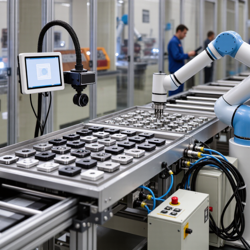
Step feeders lift parts in small increments, separating them before a linear track carries them onward. Their gentler motion can suit larger or easily damaged components, but footprint and cycle rate vary by design. Flexible systems combine a flat vibratory tray, camera-based recognition, and a robot that picks parts from changing positions. This reduces the need for dedicated tooling when products change often. It is not automatic. Vision performance depends on lighting, contrast, and part overlap; a shiny washer can be surprisingly ambiguous. Test with actual production parts, not ideal samples. Compare usable throughput, jam recovery, noise, cleaning access, and changeover time. A feeder that runs quickly in a demonstration may still need frequent operator attention on a dusty line.

How to Choose the Right Flexible Feeding System?

Compare feeder types by part-mix flexibility and orientation control. Ratings are qualitative (1 = low, 5 = high); actual performance depends on part geometry, setup, and system design.

Operating principles: Vibratory bowl feeders use vibration and shaped tracks to orient parts; centrifugal feeders use a rotating disk to move and separate parts; step feeders lift parts in stages onto a track; vision-guided flexible feeders present bulk parts for camera inspection and robotic picking. Bowl and centrifugal systems can suit high-volume runs of consistent parts, while vision-guided systems can reduce changeover effort for mixed part requirements.

Evaluate Accuracy, Maintenance, Safety, and Total Cost

How to Choose the Right Flexible Feeding System?

Evaluate Accuracy, Maintenance, Safety, and Total Cost

A flexible feeding system should match the parts you actually run, not just the clean samples in a sales demonstration. Test mixed batches, different orientations, and the smallest components. Track misfeeds, recovery time, and output over a full shift. A fast cycle means little if an operator must stop the line every few minutes. Keep the results. Memory gets optimistic.

Maintenance affects uptime as much as accuracy does. Ask how often tracks, sensors, and contact surfaces need cleaning or adjustment. Check whether routine service can be done with common tools, and whether wear parts are easy to access. A system that performs well on day one may drift as parts or surfaces change. That is easy to underestimate.

Safety checks should cover guarded moving parts, emergency stops, and safe access during jams. Watch an actual jam-clearance task; the awkward reach is often more revealing than a checklist. Finally, compare total cost across the expected service life. Include integration, training, spare parts, downtime, and energy—not only the purchase price. Estimates are imperfect, and your production mix may change. Leave room for that uncertainty.

How to Choose the Right Flexible Feeding System? — Evaluate Accuracy, Maintenance, Safety, and Total Cost
Feeding System Best Suited For Presentation Accuracy Maintenance Considerations Safety Considerations Relative Total Cost of Ownership Key Trade-Off
Vibratory bowl feeder Small, durable parts with a consistent shape and a stable, high-volume production requirement. High for a well-tuned, dedicated part; performance can decline with part variation, surface changes, or wear. Requires periodic track, spring, and drive checks. Part-specific tooling may need adjustment or replacement when the part changes. Enclose moving tracks where needed; assess noise and pinch points, and provide guarding and safe access for clearing jams. Often low to medium for long runs of one part. Changeover tooling and engineering can increase costs across multiple part types. Efficient for a stable part family, but less adaptable to frequent product changes.
Centrifugal feeder Small components that need continuous, high-speed feeding, especially when gentle handling is important. High when part geometry and feed settings are consistent; orientation capability depends on the part and separator design. Typically needs regular cleaning and inspection of the rotating disc, guides, and separation area. Settings may require tuning for new parts. Guard rotating components and interlock access panels where appropriate. Follow lockout procedures before maintenance. Medium. Throughput can be advantageous, but setup, change parts, and integration contribute to lifecycle cost. Can offer fast, gentle handling, but is not equally suitable for every shape or orientation requirement.
Flexible feeder with vision guidance Mixed or frequently changing small parts where programmable presentation and robotic picking are useful. High when parts are distinguishable in the camera view and lighting, calibration, and pick settings are maintained. Needs camera and lighting checks, calibration, software support, and cleaning of the presentation surface. Recipes require validation after changes. Assess robot reach, guarded or monitored access, emergency stops, and safe recovery procedures for the complete integrated cell. Often high initial investment, with potential savings when it reduces dedicated tooling and supports many part types. Offers flexibility, but performance depends on vision conditions, robot integration, and suitable part presentation.
Step feeder Parts that are larger, heavier, or more prone to damage in conventional vibratory feeding. Good for controlled singulation; final orientation accuracy depends on downstream guides and part geometry. Inspect lifting elements, guides, and wear surfaces. Mechanical access and replacement-part needs depend on the design. Guard reciprocating and lifting mechanisms, control pinch points, and isolate power before clearing or servicing the unit. Medium. Durable operation may suit demanding parts, though the system can take more space and require dedicated setup. Handles challenging parts well, but may not match the speed or compactness needed for every application.

Note: Ratings and cost levels are comparative guidelines, not guaranteed specifications. Actual accuracy, throughput, maintenance needs, and total cost depend on the part, required orientation, operating hours, changeover frequency, integration, and safety requirements.

Select and Validate the System for Your Application

How to Choose the Right Flexible Feeding System?

Select and Validate the System for Your Application

Start with the part, not the machine. Record its dimensions, weight, surface finish, and any features that affect orientation. A smooth plastic cap may behave differently from a stamped metal clip, even at the same feed rate. Define the required output, acceptable misfeeds, and available space. Check how the feeder will connect to sensors, controls, and downstream equipment. Flexibility matters most when product changes are frequent, but changeover time should be measured, not assumed.

Tips: Test representative parts, including the smallest, largest, and least consistent examples. Watch for scuffs, jams, and orientation errors. Keep results.

A supplier demonstration is useful, but it may not reflect your actual parts or production conditions. Validate with samples from different batches and run the system long enough to reveal inconsistent feeding. Measure sustained output, recovery after a stoppage, noise, and the time needed for changeovers. It is tempting to choose the fastest result, yet stable performance may matter more than a brief peak. Document settings and failure points. One test will not answer everything; that is a reason to test again, not to guess. Compare options using the same parts, targets, and acceptance criteria before selecting a system.

Scroll to Top
Scroll to Top