
Choosing an Iron Ball Valve is not simply a matter of matching the pipe size. The right selection depends on the fluid, operating pressure, temperature range, flow requirements, and installation environment. An iron body may suit many water and general-service systems, but the word “iron” alone does not confirm that a valve is suitable. Body grade, ball and stem materials, seat composition, and end connections all affect performance. Small details matter. A valve exposed to grit, chemical additives, outdoor moisture, or frequent operation may need different materials and maintenance. A mismatch can lead to leakage, difficult operation, or premature wear.
This guide outlines practical checks for comparing valve options. Start with the manufacturer’s pressure and temperature ratings, then confirm that the wetted materials are compatible with the actual fluid. Check whether the port design provides the flow capacity your system needs, and whether the connection type fits the existing line. Manual and actuated models also have different space and control requirements. Ball valves are commonly used for shutoff; do not assume every model is suited to throttling. That distinction is easy to overlook. A specification sheet can appear complete while leaving out real operating conditions, such as temperature swings or occasional solids. Verify those details with reliable product documentation or a qualified supplier before purchase. The best choice is the one that matches the service conditions, not merely the lowest price or a familiar label.
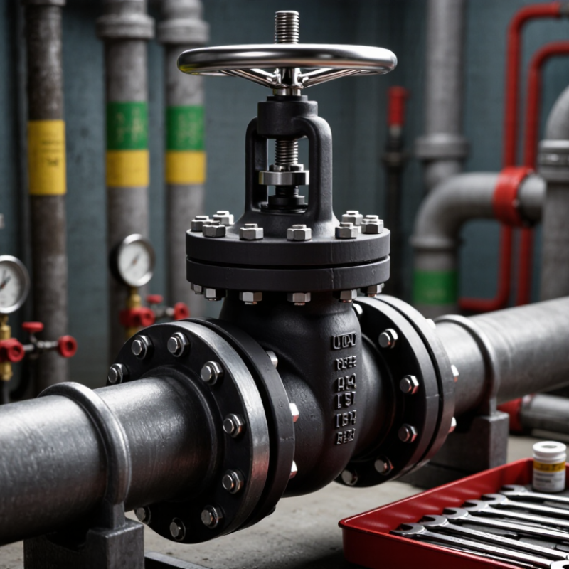
An iron ball valve usually has a cast-iron body, a spherical closure, and seats that seal around the ball. Turn the handle one quarter-turn, and the ball’s bore aligns with the pipe; turn it again, and the flow stops. Simple motion. The actual assembly may be less simple: the ball and seats can use different materials, so “iron” does not describe every wetted part.
For pressure-containing castings, ASTM A126 Class B specifies a minimum tensile strength of 31,000 psi for gray iron. That figure describes material strength, not the valve’s permitted working pressure. It is an easy distinction to miss. Check the valve’s pressure-temperature rating, connection type, and fluid compatibility instead of choosing by body material alone. In a plant room, also consider how often the valve will cycle and whether grit could score its seats. I would verify those details against the service conditions; a familiar-looking handle is not proof that the valve fits the job.
An iron ball valve should be chosen for the fluid it will actually handle, not just the pipe size. Check whether the liquid is corrosive, abrasive, viscous, or likely to carry grit. Fine particles can score the ball or seat, causing leakage over time. The fluid’s chemistry also matters: iron body materials and seal compounds do not suit every process. Consider cleaning fluids and occasional flushes, too. Small details count.
Next, compare the maximum operating pressure with the valve’s rating at the expected temperature. Ratings can change as temperatures rise, so check the technical data for the exact valve design. Include pressure surges, pump starts, and the pressure difference across a closed valve. Don’t size only for steady conditions. Temperature affects both the body and the seats; repeated heating and cooling may also shorten seal life. One easy detail to miss is a brief cleaning cycle with hotter fluid. It may be worth checking. Confirm the operating range, materials, and pressure limits against reliable product documentation, and ask a qualified supplier when the process conditions are uncertain. A little uncertainty is better acknowledged than hidden.
Choosing an iron ball valve starts with the fluid, temperature, and pressure—not just the pipe material. Cast iron can suit many water-service applications, while carbon steel or stainless steel may be better for higher pressures or corrosive fluids. Confirm chemical compatibility with the valve body, ball, and seats; a compatible body alone is not enough. The 2016 NACE IMPACT study estimated corrosion costs at $2.5 trillion annually, about 3.4% of global GDP. That figure covers many industries, not valve failures alone, but it shows why corrosion deserves attention. Material charts help, yet real fluid conditions can be messy.
Size the valve for the required flow and pressure drop, not simply the line’s nominal diameter. A reduced-port valve can restrict flow, while an oversized valve may control poorly in throttling service. Check operating pressure and temperature against the applicable valve rating, such as ASME B16.34. Small details matter.
Choose threaded, flanged, or welded ends to match the piping system and maintenance plan. Threaded connections are compact, but can be awkward to inspect in tight spaces. Flanges ease removal; they also need room for bolts and a gasket. Welded ends provide a permanent joint, so replacement takes more work. Verify the end dimensions and pressure class before ordering. I would not assume a matching nominal size guarantees a fit; that shortcut is easy to regret.
For an iron ball valve, compare ball support, port size, and operating method against the actual service. A floating ball uses line pressure to press the ball against the downstream seat. A trunnion-mounted ball is supported at both ends and can reduce operating torque in larger or higher-pressure designs. Full-port valves have openings close to the pipe’s inside diameter, helping limit flow restriction. Reduced-port valves are often more compact, but may increase velocity and pressure loss. Fit matters.
Check the valve’s pressure rating at operating temperature, not just its nominal pressure class. ASME B16.34-2020 provides pressure-temperature rating tables by material and class; the applicable rating changes with temperature. For operation, a lever may suit frequent manual use, while a gear operator can make larger valves easier to turn. Actuator sizing should use the valve’s required torque under the expected differential pressure. ISO 5211:2017 specifies actuator-mounting dimensions, but does not determine that torque. Not always obvious.
Tips: Compare the port diameter with the pipe’s internal diameter, then check the manufacturer’s flow and torque data. Confirm seat material and service conditions together; I would not assume a cheaper, smaller port is a harmless compromise.
How to Choose the Right Iron Ball Valve?
Checking Standards, Installation, and Maintenance Needs
A suitable iron ball valve must match the fluid, pressure, temperature, and connection type. Check its pressure-temperature rating against ASME B16.34, and confirm the end connection fits the piping standard. For flanged valves, verify dimensions and facing before ordering. ISO 5208 provides pressure-testing procedures for industrial valves; ask for documented test results, not just a stated class. These checks matter because “iron” alone does not describe the body grade or operating limits. A specification can look complete and still miss a temperature change during startup.
Installation affects service life. Remove grit and weld debris from the line, support heavy piping, and avoid forcing misaligned flanges together. Follow the valve’s flow and mounting guidance; designs differ. Keep the handle accessible, with enough room for a full quarter-turn. Do not use a standard on-off ball valve for prolonged throttling unless its design permits it. The U.S. Department of Energy’s Improving Pumping System Performance sourcebook reports that system-level improvements can reduce pumping energy use by 20–50 percent. That figure is not a valve-only saving, but poor flow control can waste energy.
Small details matter. Before maintenance, isolate and depressurize the line, then verify it is safe to open. Inspect for external corrosion, seat leakage, stiff operation, and damaged handles. Use a compatible lubricant only when the valve instructions allow it. Record inspection dates and leakage findings; patterns often reveal problems earlier than a sudden failure. Inspection intervals should reflect service conditions, not a convenient calendar alone. That part is easy to overlook.
| Decision Area | What to Check | Selection Guidance | Installation and Maintenance Notes |
|---|---|---|---|
| Body material | Confirm whether the body is gray cast iron or ductile iron, and check the stated material grade. | Choose a material suitable for the fluid, pressure, temperature, and external environment. Ductile iron generally has greater toughness than gray iron, but the valve’s published ratings and service limits govern selection. | Check the body and end connections for damage before installation. Do not use a valve with cracks, impact damage, or distorted flanges. |
| Pressure and temperature | Review the manufacturer’s pressure–temperature rating for the complete valve, including body, trim, and seats. | Select a valve whose rating covers the maximum operating conditions and foreseeable surges. Do not infer the valve rating from the pipe class or body material alone. | Keep operating conditions within the documented limits. Consider pressure spikes, temperature changes, and the effects of the conveyed fluid. |
| Applicable standards | Check the specified design, inspection, testing, flange, and face-to-face standards. | Use standards that match the valve type and service. ASME B16.1 covers cast-iron pipe flanges and flanged fittings; ASME B16.10 covers face-to-face and end-to-end dimensions for covered valves. ISO 5208 and API 598 address pressure testing of metallic valves within their respective scopes. Confirm the edition and applicability with the supplier and project specification. | Verify that the valve’s flange drilling, dimensions, and test documentation match the connected equipment and project requirements. |
| Fluid and seat materials | Identify the fluid, concentration, suspended solids, cleanliness, and required seat or seal material. | Confirm chemical and temperature compatibility for all wetted materials. A material suitable for water may not be suitable for oils, solvents, acids, or other process fluids. | Flush the line before commissioning where appropriate. Debris can damage seats and cause leakage or difficult operation. |
| Valve size and flow | Compare nominal pipe size, valve port design, flow coefficient, and expected flow rate. | Choose a full-port or reduced-port design based on flow capacity, pressure drop, and space requirements. A valve’s nominal size alone does not establish its flow capacity. | Install in the orientation permitted by the valve instructions and provide enough clearance for the handle or actuator to operate fully. |
| End connections | Confirm flange standard, pressure class, facing, bolt pattern, and gasket requirements. | Ensure both mating ends are compatible. For flanged cast-iron connections, verify the applicable flange dimensions and rating rather than assuming that similar nominal sizes will fit. | Align piping without forcing the valve into position. Tighten bolts evenly using the specified procedure; avoid excessive loads on the valve body. |
| Operating purpose | Determine whether the valve is intended for on/off isolation or frequent adjustment. | Ball valves are generally used for open/close service. Use a valve specifically rated for throttling if flow regulation is required. | Move the valve through its full travel as directed. Do not force the handle or actuator against a mechanical stop. |
| Installation location | Check access, support, environmental exposure, and the manufacturer’s flow-direction or orientation instructions. | Choose a location that allows safe operation and inspection. Protect the valve from loads caused by unsupported pipework, vibration, freezing, or corrosive surroundings. | Support adjoining pipework independently where needed. Isolate and depressurize the line before installation, adjustment, or service. |
| Testing and documentation | Request the applicable pressure-test and inspection records, material details, and operating limits. | Confirm that testing was performed to the standard and acceptance criteria required by the project. A test standard does not by itself confirm suitability for every application. | After installation, check joints and operation using the site’s approved commissioning procedure. Follow applicable safety rules and avoid exceeding the valve’s rated test pressure. |
| Maintenance plan | Review the valve design, service conditions, inspection access, and any manufacturer-recommended maintenance interval. | Set inspection frequency according to operating conditions, criticality, and observed performance rather than assuming a universal interval. | Inspect for external leakage, corrosion, damage, and abnormal operating torque. Follow the manufacturer’s instructions for seat, seal, and actuator service; depressurize and drain the line before disassembly. |
"*" indicates required fields