
Choosing the right Lead Flange starts with the conditions it must withstand, not the shape that looks familiar. Pipe size, facing type, bolt pattern, pressure, temperature, and the connected materials all matter. A mismatch can cause leaks, difficult installation, or early failure. Small details count. Measure the pipe and mating flange carefully, then check the manufacturer’s drawings and ratings before specifying a part.
For this introduction, the named specialist and quotation below are illustrative, not a verified published attribution: piping engineer Daniel Mercer says, “A flange is right only when its material, dimensions, and service conditions agree.” Treat that as a practical selection principle, not a substitute for documented specifications. Lead is toxic, so a Lead Flange should be considered only where its use is permitted and appropriate for the application. Confirm material suitability, handling requirements, and applicable local rules with qualified professionals. Do not rely on appearance alone. A clean finish cannot confirm composition or performance. This guide outlines the checks that help project teams compare options, ask suppliers useful questions, and document their decisions. Some projects may still require specialist review; that is worth allowing time for.
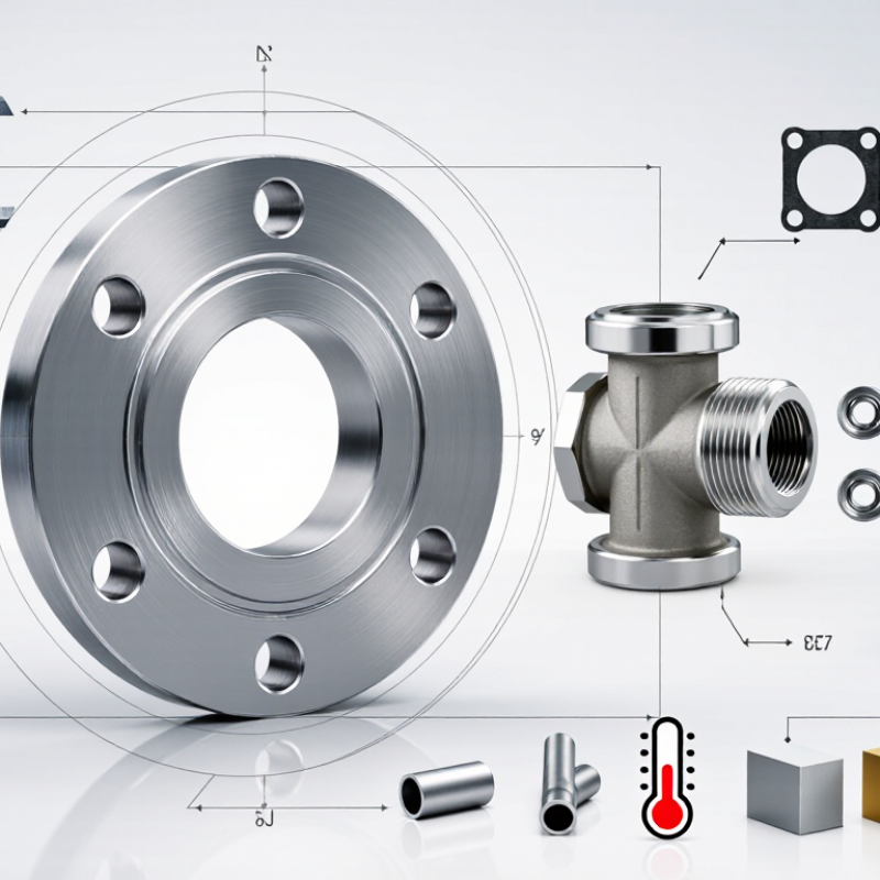
A lead flange is a pipe or equipment connection made from lead, or a steel flange with a lead lining. The term can vary between drawings and suppliers. That distinction matters. Lead is soft and malleable, so a lined steel flange usually provides the structural strength while the lead layer helps protect surfaces from selected corrosive substances. It is not a universal corrosion solution.
Lead-lined flanges may appear on chemical tanks, process piping, and equipment handling compatible fluids. They can also connect lined sections to other components, where careful alignment helps prevent damage to the lining. Lead’s resistance depends on the specific chemical, its concentration, temperature, and operating conditions. Check those details against qualified engineering guidance and applicable project requirements. Older drawings can be unclear, so confirm the actual construction before specifying a replacement.
Tips: Ask whether “lead flange” means solid lead or lead-lined steel. Verify pressure, temperature, dimensions, facing, and fluid compatibility. Inspect the lining near bolt holes and the sealing face; small defects can matter. Don’t assume a familiar service is automatically suitable. A compatibility review may feel cautious, but it is cheaper than discovering a mismatch after installation.
Lead flanges may be solid lead, lead-lined steel, or custom components designed for a specific connection. These are not interchangeable. Solid lead is soft, so it should not be treated as a routine load-bearing pressure flange without qualified engineering review. Lead-lined designs use a structural backing, while the lead layer provides a compatible contact surface for the intended service.
Common flange geometries include flat-face, raised-face, slip-on, threaded, and blind designs. The right option depends on the mating equipment, piping layout, and how the joint will be assembled. Check the nominal pipe size, outside diameter, bolt-circle diameter, hole count, bore, and flange thickness. Also confirm the facing, gasket material, lead composition or lining thickness, and operating temperature and pressure. Small mismatches matter. A bolt pattern that looks close may still prevent a reliable fit.
Ask the supplier for dimensional drawings and material documentation, then compare them with the project specification. Verify chemical compatibility for the actual fluid; lead is not suitable for every process. Catalog labels alone can be misleading, especially when “lead flange” describes a lining rather than the whole component. I would not skip this distinction. If the connection carries pressure or structural loads, have a qualified engineer confirm the design and applicable rating before installation.
How to Choose the Right Lead Flange for Your Project
How to Assess Project Requirements and Operating Conditions
Start with the service, not the nominal pipe size. Record the fluid, design pressure, temperature range, pressure surges, and expected maintenance access. Confirm what “lead flange” means in your design: solid lead, lead-lined, or a lead component joined to a metal flange. These are not interchangeable. Check chemical compatibility and how the assembly will handle vibration, piping loads, and gasket compression. Small details matter. A flange may fit the drawing but still fail the service conditions.
Use published ratings carefully. ASME B16.5-2020, Table 2-1.1, lists a 285 psi pressure rating at 100°F for a Class 150 flange in material Group 1.1. That is an illustrative carbon-steel rating, not a rating for lead or lead-lined parts. Verify the applicable material group, temperature, flange class, and governing design code. Ask for documented pressure and temperature limits for the lead component, plus test and inspection records. In practice, the weakest part of the joint sets the limit. One uncertainty often remains: actual gasket compression can differ from the drawing, especially where connected piping shifts during installation. Allow for that in the review, rather than assuming a perfect fit.
These example temperatures help illustrate an initial operating-condition check; they are not flange ratings or design recommendations. Lead melts at approximately 327.5°C, but its melting point is not a safe operating limit. Confirm pressure capacity, applicable codes, chemical compatibility, and lead-exposure controls with qualified engineering guidance before specifying any lead component.
How to Choose the Right Lead Flange for Your Project
The word “lead” needs checking before you select a flange. It may describe solid lead, a lead-lined assembly, or a project-specific component. These are not interchangeable. Lead is soft and can deform under sustained loads, so do not assume a lead part is suitable as a pressure-retaining flange. Confirm its intended function and design documentation.
Choose materials for the fluid, temperature, and surrounding environment. Carbon steel may suit some services, while stainless steel or an alloy may be needed for corrosion resistance. If lead lining is specified, check that the lining and flange body are compatible with the process. A detail that is easy to miss: the gasket must suit both the fluid and the flange-face finish.
Match the flange size to the pipe’s nominal size, bore, facing, and bolt pattern. A flange that looks close may still misalign at the bolt holes. Then verify its pressure-temperature rating against normal operation and possible surges. Pressure class alone does not tell the whole story; temperature can reduce allowable pressure. I would pause if drawings, material specifications, or rating data disagree, and ask the responsible engineer to resolve the mismatch before ordering.
| Selection Factor | Relevant Data or Options | How to Select | Important Verification |
|---|---|---|---|
| Lead material properties | Pure lead has a density of approximately 11.34 g/cm³ and a melting point of approximately 327.5°C (621.5°F). It is soft and has relatively low mechanical strength. | Consider lead primarily where its shielding, lining, or chemical-service properties are required—not as a default structural pressure-boundary material. | Confirm the lead grade, fabrication method, temperature limits, and compatibility with the process fluid. Lead’s resistance to corrosion depends on the specific chemical environment. |
| Application and flange function | Lead components may be used in specialized shielding, lining, sealing, or low-stress service. A lead flange is not interchangeable with a standard steel pressure-pipe flange. | Identify whether the lead part is intended to contain pressure, provide shielding, form a lining, or connect to another component. | Have a qualified engineer assess mechanical loads, creep, joint design, support, and exposure conditions before using lead in a connection. |
| Nominal pipe size | For many conventional piping flanges, ASME B16.5 covers NPS ½ through NPS 24. NPS is a nominal designation; it is not the measured outside diameter. | Match the flange to the mating pipe’s nominal size, schedule or wall thickness, facing, and bolt pattern. Do not select by nominal size alone. | Check the applicable dimensional standard and the actual mating component. Standard flange dimensions do not establish that a lead flange is suitable for pressure service. |
| Pressure rating | Conventional flange classes include Class 150, 300, 600, 900, 1500, and 2500 under relevant piping standards. These ratings depend on material and temperature. | Do not assign a standard pressure class to a lead flange unless a governing design code and qualified engineering analysis specifically support it. | There is no general ASME B16.5 pressure-temperature rating for a flange made from lead. Verify the complete joint design, operating pressure, temperature, and applicable code. |
| Mating materials | Connections may involve lead, steel, stainless steel, or other materials, each with different strength, expansion, corrosion, and sealing characteristics. | Choose compatible mating materials and a joint method designed for the specific service. Avoid assuming that standard bolts and gasket arrangements are suitable for lead. | Assess galvanic effects where dissimilar metals contact, as well as gasket compatibility and the risk of lead deformation under bolt load. |
| Temperature and process conditions | Lead’s melting point is about 327.5°C, but its usable service temperature can be far lower because strength and dimensional stability are limiting factors. | Evaluate maximum and minimum operating temperatures, pressure cycling, vibration, and external loads together—not as separate checks. | Use documented design limits for the exact lead component and service. The melting point alone is not a safe operating-temperature limit. |
| Fabrication and inspection | Lead parts may be cast, machined, or formed depending on the design and manufacturer’s process. | Specify dimensional tolerances, surface finish, connection details, and inspection requirements on the project drawing. | Require suitable quality documentation and follow applicable workplace controls for lead exposure, including handling, machining, and joining precautions. |
| Final selection decision | Selection depends on the function, dimensions, process fluid, temperature, pressure, loading, and governing project requirements. | Use a lead component only when its purpose and engineering limits are clearly defined. For ordinary pressurized piping, select a code-rated flange material suitable for the service instead. | Obtain approval from the responsible piping or mechanical engineer before procurement or installation. |
Safety note: This guide is for preliminary selection only. Lead is toxic, and a lead flange should not be treated as a standard pressure-rated piping flange. Confirm design suitability, regulatory requirements, and safe handling procedures with qualified professionals.
A lead flange must match more than the pipe diameter. Check the nominal size, flange outside diameter, bolt-hole pattern, and facing dimensions against the mating component’s drawing. A tape measure can help confirm basic dimensions, but it cannot verify pressure ratings or material suitability. Use the project specification and supplier documentation for those details. Small mismatches matter.
Check the service conditions before ordering: fluid or gas, operating pressure, temperature, and contact with other materials. Lead is relatively soft and can deform under uneven loads, so confirm that the flange is suitable for the application rather than assuming it is. For pressure service, ask a qualified engineer to verify the design and rating. Then review the installation instructions. Clean the faces, align the pipework without forcing the joint, and use the specified gasket and fasteners. Tighten evenly in a cross pattern, following the stated torque guidance; more force is not necessarily better. Support the connected pipe so its weight does not pull on the flange. One detail is easy to miss: a neat-looking fit may still be wrong if the bolt pattern or sealing face differs. Check twice.
"*" indicates required fields