
Cylindrical Fenders are simple-looking rubber units designed to cushion contact between a vessel and a fixed structure. Their round profile can be mounted vertically or horizontally along quay walls, pontoons, and berthing faces. When a boat presses against the rubber, the fender deforms and helps reduce direct impact on both surfaces. The amount of protection depends on its dimensions, rubber compound, installation, and the forces involved.
Marine fender specialist Alex Morgan sums up the design principle: “A fender works best when its shape and mounting suit the vessel, berth, and actual impact conditions.” In practice, cylindrical units are often chosen for workboats, small craft, and locations needing straightforward, replaceable protection. A row of black rubber cylinders can be seen along a landing stage, each spaced to meet the hull at likely contact points. Simple to recognize.
But simple does not mean suitable everywhere. A cylindrical fender may not provide enough energy absorption for a large vessel or a demanding berthing site. Designers also need to consider vessel approach angle, tide range, fixing strength, and the structure behind the rubber. These details are easy to underestimate. This guide explains what Cylindrical Fenders are, how they work, where they are commonly used, and what to check before specifying them. Actual performance varies by product and installation, so project requirements should be reviewed with a qualified marine engineer.
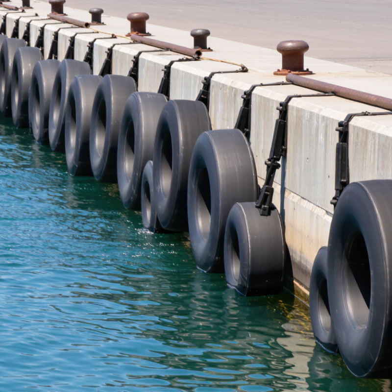
A cylindrical fender is a long, tube-shaped rubber buffer fitted between a vessel and a quay, pile, or dolphin. It may be hollow or solid, and is commonly secured with chains, rods, or brackets. When a hull presses against its curved surface, the rubber compresses and spreads contact along a narrow strip rather than one hard point. Simple in appearance.
Cylindrical fenders are used where a straightforward, flexible contact surface is useful, including jetties and smaller berthing structures. They can be installed horizontally or vertically; vertical mounting can maintain contact as water levels change. PIANC’s 2002 Fender Guidelines calculate berthing energy using vessel mass, approach speed, and correction factors. In that method, energy varies with speed squared: doubling approach speed means four times the kinetic energy, with other factors unchanged. That matters. A small-looking change in speed can therefore alter the required fender performance substantially. Selection still depends on vessel size, berth geometry, mounting, and expected contact conditions. A tidy drawing can hide those details. Cylindrical shapes are not automatically suitable for every berth, so engineers check the expected energy and the fender’s rated reaction and deflection before specifying one.
Cylindrical fenders are tough, hollow rubber bodies fitted to quay walls, piers, or vessels. When a hull presses against one, the cylinder compresses and changes shape. Its rubber wall bends under load, absorbing part of the impact instead of transferring it all at once to the structure. The movement is visible. A loaded fender may flatten slightly, then recover when the pressure eases.
Impact absorption depends on the rubber compound, cylinder dimensions, and how the fender is mounted. A larger contact area can spread pressure along the hull, while a flexible body helps soften contact during berthing. The fender does not make a collision harmless; it reduces and manages the force. That distinction matters. Installation also affects performance: loose supports or uneven contact can concentrate stress in one area.
In practice, crews should check for deep cuts, cracking, hardening, and movement around mounting points. These signs can indicate reduced flexibility or poor load transfer. Conditions vary, so a single visual check cannot confirm performance. I have to admit, judging the remaining life by appearance alone is imperfect; operating loads and material condition matter too. A fender that looks intact may still have become stiffer with age or exposure.
| Topic | Typical Information | How It Relates to Impact Absorption or Use |
|---|---|---|
| Basic form | A cylindrical fender is an elongated, round-profile fender, commonly made from marine-grade rubber. It may be supplied as a solid or hollow section, depending on its design. | The curved surface makes contact with a vessel or structure and compresses under load, helping reduce direct contact forces. |
| How impact is absorbed | When compressed, the rubber deforms and stores and dissipates part of the impact energy. The energy absorbed is represented by the area under the force–deflection curve. | As the fender deflects, it helps slow the vessel’s approach and reduces the peak force transmitted to the berth, subject to the fender’s design limits. |
| Key performance measures | Energy absorption, reaction force, allowable deflection, and the fender’s dimensions are commonly considered in selection. | Energy absorption indicates the impact energy the fender can manage; reaction force indicates the load passed to the supporting structure. |
| Common applications | Quay walls, jetties, dolphins, pile-supported berths, and other waterfront structures; also used in some vessel-to-vessel or guide-contact applications. | The cylindrical profile can provide a simple, continuous contact surface along a berth or around a pile. |
| Typical installation orientation | May be installed horizontally or vertically, depending on the berth layout and the vessel’s contact area. | Orientation helps position the fender where hull contact is expected and can accommodate different water levels or vessel geometries. |
| Mounting considerations | Installation methods can include chains, rods, brackets, or other restraints selected for the fender design and site conditions. | Secure mounting keeps the fender in its intended position and transfers its reaction load to the supporting structure. |
| Design factors | Performance depends on dimensions, rubber compound, fender geometry, temperature, loading rate, angle of contact, and the supporting structure. | These factors affect deflection, reaction force, and energy absorption, so performance should be checked against the relevant design data. |
| Selection checks | Consider vessel displacement and approach speed, berth layout, available mounting space, expected contact conditions, and the structural capacity of the berth. | A suitable system must manage the design impact while keeping both fender reaction and structural loads within acceptable limits. |
| Inspection and maintenance | Inspect for cracking, cuts, excessive wear, deformation, loose restraints, and corrosion or damage to mounting hardware. | Routine checks help identify damage that could reduce performance or cause the fender to detach or move out of position. |
Cylindrical fenders are commonly made from natural rubber, synthetic rubber, or a blend chosen for the working environment. Rubber flexes under pressure and helps absorb impact when a vessel meets a quay or another structure. Some designs contain steel reinforcement or a central chain to support suspension and reduce unwanted movement. Construction varies, so diameter alone cannot show how much energy a fender can absorb. Small details matter. In service, inspect the surface, attachment points, and contact area for cracking, wear, or deformation, especially after repeated berthing.
Design features affect how a fender behaves. A smooth cylinder may roll slightly against a hull, spreading contact across its surface. Ribbed textures can provide more grip in some installations. End fittings and chains should suit the mounting arrangement and exposure to saltwater, sunlight, and abrasion. There are trade-offs: a tougher outer layer may resist wear but alter flexibility. Thicker is not always safer. Vessel movement, impact loads, and available clearance also matter. Specifications are useful, but they may not capture awkward dock geometry or changing water levels. Those site details deserve a closer look.
Cylindrical fenders are commonly installed along quay walls, jetties, and piles serving small vessels. Their simple shape suits workboats, tugs, barges, and service craft that may approach at changing angles. They can be mounted vertically or horizontally, depending on the berth layout and likely contact points. Angles matter. On dolphins and exposed corners, they provide a compliant surface where a vessel might otherwise meet a hard edge. PIANC’s Working Group 33 guidelines emphasize matching fender-system performance to vessel energy, berthing conditions, and structural limits—not selecting by shape alone.
They are also used between vessels during ship-to-ship operations and alongside service platforms, where contact can shift with tide and movement. The scale of port activity makes careful placement important: UNCTAD’s Review of Maritime Transport 2024 reports that global maritime trade reached about 12.3 billion tonnes in 2023. That figure describes the wider operating environment, not demand for any one fender type. A cylindrical unit may suit a compact berth, but its energy capacity, spacing, mounting, and wear condition still need checking. A neat installation can still be wrong. In practice, poor positioning may leave the vessel’s bow or hull fittings exposed.
Cylindrical fenders are often selected for quay walls and piles where vessels need simple, continuous contact protection. Choosing one starts with the berth, not the catalogue: note vessel size, approach speed, contact angle, tide range, and available clearance. PIANC’s 2002 Guidelines for the Design of Fender Systems calculate berthing energy using ½MV², adjusted by coefficients for factors such as eccentricity and added water mass. Those inputs matter. A fender that looks large may still provide inadequate energy absorption or create excessive reaction force.
Check the fender’s diameter and length against the vessel’s likely contact area and the structure’s load capacity. Confirm rubber performance, allowable deflection, and whether the fender can tolerate repeated rubbing or impact. Small details matter. A short fender may leave gaps as a vessel moves with the tide; a rigid mounting can transfer damaging loads into weak concrete. Even careful calculations leave uncertainty, especially where operating speeds are only estimated.
During installation, keep the fender aligned with the expected contact path and use suitable anchors or retaining chains for the site conditions. Verify clearances at low and high water, then inspect fasteners, wear, and deformation after commissioning. PIANC’s guidance supports a system-level design, but site measurements still decide whether the installation works. A tidy drawing is not proof. Recheck assumptions against actual vessel movements, because real berthing is rarely perfectly straight.
"*" indicates required fields