What Is Diaphragm Wall Equipment and How Does It Work?
Diaphragm walls help create deep, stiff barriers for basements, transit stations, and excavations beside existing buildings. Their performance depends on more than wall thickness. Ground conditions, panel joints, slurry control, and concrete placement all matter.
Diaphragm Wall Equipment turns this demanding sequence into a controlled construction process. A grab or hydromill excavates narrow panels, while bentonite or polymer slurry supports the trench. Reinforcement cages are lowered into place, and concrete is poured through a tremie pipe, displacing the slurry upward. The scene is precise: a suspended cage, a deep slurry-filled trench, and concrete flowing continuously from below. Small interruptions can create serious quality concerns.
Professional guidance helps explain why these details matter. The EFFC/DFI Guide to Tremie Concrete for Deep Foundations discusses concrete placement and quality control in deep, slurry-supported excavations. The ICE Specification for Piling and Embedded Retaining Walls provides a framework for specifying and checking piling work. Neither replaces project-specific engineering or careful site supervision. Conditions vary. So does the risk.
A named expert quotation should be checked against its original publication before use. No source-verified quotation from a diaphragm-wall specialist was included with the material provided, so attributing a memorable line here would risk inventing evidence. That gap matters: reliable explanations should distinguish documented guidance from opinion. The sections ahead examine the equipment, operating sequence, and practical checks that shape a diaphragm wall’s quality.
What Is Diaphragm Wall Equipment?
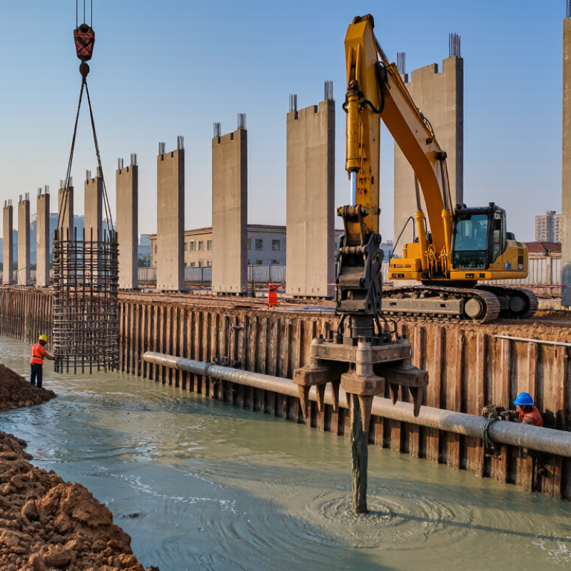
Diaphragm wall equipment is the machinery and tooling used to excavate, support, reinforce, and fill narrow trenches in the ground. The main excavator is usually a hydraulic grab or a cable-operated grab; hard or uneven ground may require a cutter with rotating wheels. A crane lowers the tool into a trench filled with bentonite or polymer slurry, which helps support the sides before concrete is placed. It is substantial equipment.
A slurry treatment plant removes soil particles and checks fluid properties. A desanding unit, storage tanks, pumps, and pipes keep the slurry circulating. Once excavation reaches the design depth, workers lower a steel reinforcement cage using a crane. Tremie pipes then place concrete from the bottom upward, displacing the slurry. FHWA’s Earth Retaining Structures manual (NHI-07-071, 2008) describes diaphragm walls commonly about 0.6–1.2 metres thick; exact dimensions depend on ground conditions and design.
On site, equipment selection is not just about digging speed. A grab may be practical in softer soils, while a cutter can help maintain panel alignment in harder strata. Surveying tools track verticality, and operators check slurry condition throughout excavation. Small deviations matter. The trench can look stable at the surface while conditions below remain uncertain, so testing and experienced supervision are essential.
What Are the Main Components of Diaphragm Wall Equipment?
Diaphragm wall equipment is a working system, not a single machine. The excavation tool may be a cable-hung grab or a hydraulic trench cutter, selected for ground conditions and wall depth. A crawler crane lifts the tool and, later, the reinforcement cage. Guide walls at ground level help keep the trench aligned and provide a stable reference for positioning.
Slurry equipment supports excavation in water-bearing or unstable soils. Storage tanks hold the bentonite or polymer slurry, while pumps circulate it through hoses and the trench. A desander removes soil particles before the slurry is reused. The details matter. Blocked screens or poorly maintained hoses can slow work and affect slurry quality.
After excavation, lifting gear lowers the steel reinforcement cage into the trench. Tremie pipes then place concrete from the bottom upward, displacing the slurry. Surveying tools and depth checks help crews track alignment and excavation progress. On a muddy site, even a good setup can become awkward; access and hose routing are easy to underestimate. A checklist helps, but it cannot replace regular inspection and clear communication between the crane operator, excavation crew, and concrete team.
Where Is Diaphragm Wall Equipment Commonly Used?
What Is Diaphragm Wall Equipment and How Does It Work?
Where Is Diaphragm Wall Equipment Commonly Used?
Diaphragm wall equipment is common on dense urban sites where excavation space is tight. It helps construct deep, reinforced-concrete walls for metro stations, underground car parks, building basements, utility shafts, and flood-protection works. These walls can retain soil and limit groundwater movement. UN DESA’s World Urbanization Prospects: The 2018 Revision projects that 68% of the world’s population will live in urban areas by 2050. More people in cities can mean greater demand for underground infrastructure. The pressure is real.
During construction, a grab or cutter excavates narrow panels through soil, often under support from bentonite slurry. Crews then lower a steel reinforcement cage and place concrete through a tremie pipe. The U.S. Federal Highway Administration’s 2008 Geotechnical Engineering Circular No. 6 describes diaphragm walls among the retaining systems used for deep excavations. They are especially useful near existing buildings, roads, or rail lines, where ground movement must be controlled. But they are not a cure-all: geology, groundwater, access, and slurry handling can complicate work. Site conditions deserve close review.
Tips: Check nearby foundations and underground utilities before excavation. Track slurry properties and wall alignment throughout the work. Small deviations matter. Teams should also plan for spoil removal; cramped streets can make it harder than expected.
What Is Diaphragm Wall Equipment and How Does It Work?
Diaphragm wall equipment excavates narrow, deep trenches in panels, usually under bentonite or polymer slurry that supports the soil. A grab or hydromill removes the soil; reinforcement is lowered into the trench, and concrete is placed from the bottom up through a tremie pipe, displacing the slurry.
Where Diaphragm Walls Are Commonly Used
Indicative depth ranges for common applications. Actual wall depths depend on site geology, groundwater, structural design, and project requirements; these ranges are not design specifications.