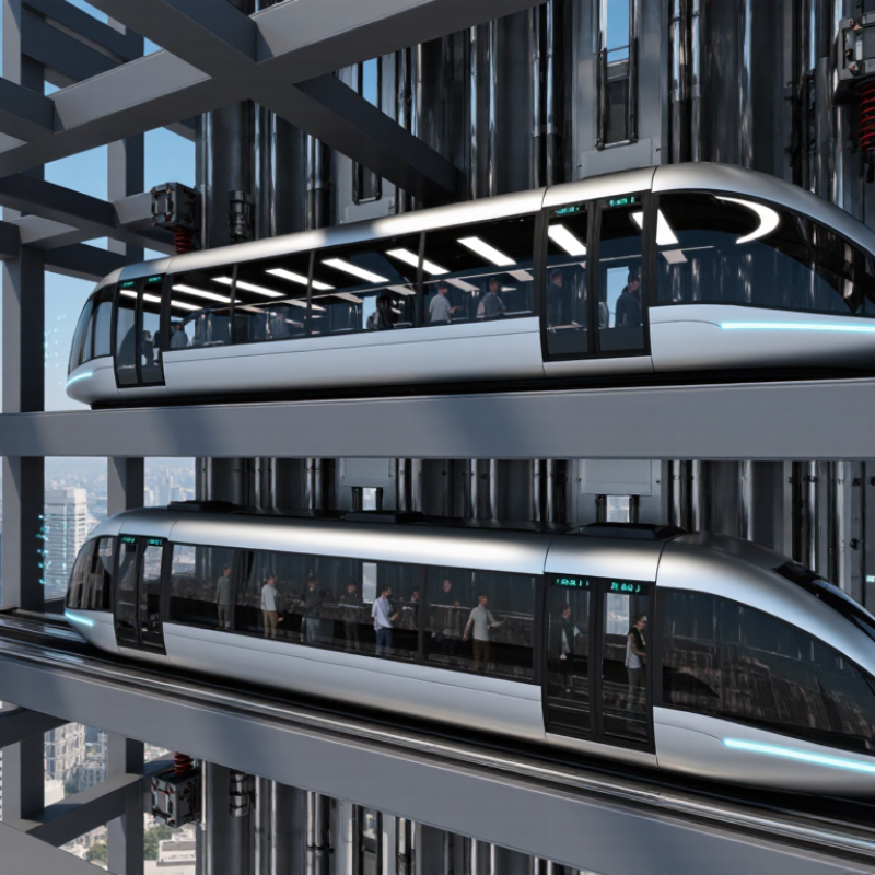
| Definition of a High-Speed Lift | There is no single universal speed threshold that legally defines a “high-speed lift.” In practice, the term is commonly used for passenger lifts operating at approximately 2.5 m/s or above. | The lift uses higher-capacity traction equipment, advanced motion control, stronger guidance systems, and more carefully designed braking and ride-comfort systems. | Higher speed increases stopping distance, aerodynamic effects, vibration, pressure changes, and the energy that must be controlled during abnormal events. | “High speed” is generally a descriptive engineering term; applicable safety requirements depend on the lift design, rated speed, travel, use, and local regulations. |
| Rated Speed | Typical high-speed passenger lift designs may operate around 2.5–10 m/s, while specialized installations can be outside this range. | Rated speed is the intended normal operating speed of the car and is used when selecting the drive, ropes, sheaves, guide rails, governor, brakes, and buffers. | Safety devices are coordinated with the rated speed and must operate reliably during overspeed and emergency conditions. | Actual limits and performance requirements must be verified against the applicable edition of the relevant lift standards and local code. |
| Traction Drive | Most high-speed passenger lifts use an electric traction machine with ropes, a traction sheave, a car, and a counterweight. | The motor turns the traction sheave; friction between the sheave and ropes moves the car and counterweight in opposite directions. Variable-speed drives provide controlled acceleration and deceleration. | Controlled torque and speed regulation help prevent harsh starts, uncontrolled movement, and excessive stopping loads. | Drive, rope, sheave, and suspension design must be assessed as a complete system rather than as isolated components. |
| Overspeed Governor | A mechanical or electromechanical monitoring device connected to a governor rope or equivalent sensing arrangement. | The governor continuously detects car speed. If the car reaches its calibrated tripping condition, it initiates the safety circuit and can mechanically actuate the car safety gear. | It provides an independent protective layer when normal drive control, braking, or another control function fails. | Governor tripping characteristics, accessibility, testing, and protective functions are addressed by the EN 81 safety framework and the approved design. |
| Governor Tripping Principle | The tripping point is set above rated speed and is selected according to the applicable safety requirements and lift configuration. | The governor must distinguish abnormal overspeed from normal operation while avoiding unnecessary trips during acceleration, leveling, or inspection movement. | Correct calibration is essential: a setting that is too low may cause nuisance trips, while one that is too high may delay protective action. | The precise tripping value is not a universal fixed number; it depends on the rated speed, governor type, and applicable standard requirements. |
| Car Safety Gear | Safety gear may be progressive or instantaneous, depending on the lift design and permitted application. | When actuated, wedges, clamps, or other gripping elements engage the guide rails and bring the car to a controlled stop or restrict its movement. | Progressive safety gear is commonly associated with higher-speed passenger lifts because it limits deceleration peaks and reduces injury risk. | Selection and type depend on rated load, rated speed, guide-rail design, stopping performance, and the applicable EN 81 requirements. |
| Ascending Car Overspeed Protection | High-speed lifts require protection against unintended excessive upward movement in addition to protection against downward overspeed. | Depending on the approved design, the system may use a monitored brake, a safety device, a governor-related function, or a combination of protective measures. | It helps limit risks caused by drive faults, brake faults, control failures, or unbalanced suspension forces. | EN 81-20 includes requirements for protection against ascending-car overspeed and unintended car movement. |
| Machine Brake | Typically an electrically released, mechanically applied friction brake, often using redundant braking elements. | When power is removed or a safety circuit opens, springs apply the brake to the traction machine shaft or another approved braking location. | The brake holds the car at a landing, assists normal stopping, and contributes to protection against unintended car movement. | Brake capacity, monitoring, redundancy, release control, and stopping performance must comply with the approved lift design and applicable standards. |
| Brake Monitoring | Common monitoring arrangements verify brake application, release status, or the consistency of redundant braking elements. | Sensors or switching devices send status information to the safety-related control system, which can prevent continued operation after a detected fault. | Monitoring helps identify a brake that fails to apply, remains partially released, or loses required performance. | The exact monitoring architecture varies by design and jurisdiction; it must be validated as part of the safety circuit. |
| Emergency Braking and Stopping | Stopping performance is determined by rated load, speed, brake torque, deceleration, traction conditions, and the applicable safety function. | When a dangerous condition is detected, the control system removes drive torque and applies the brake or another approved stopping device. | Stopping must control energy without producing unacceptable deceleration, rope slip, loss of traction, or excessive structural loads. | Stopping distances and deceleration limits are design- and test-dependent; they should not be inferred from speed alone. |
| Buffers | Buffers are installed at the bottom of the car and counterweight travel zones. Common types include energy-accumulating spring or elastomer buffers and energy-dissipating hydraulic buffers. | If the car or counterweight travels beyond its normal terminal position, the buffer absorbs or dissipates kinetic energy and limits impact forces. | Buffers are a final-travel protective device and are not intended to replace the governor, safety gear, brake, or normal terminal stopping system. | Buffer type, stroke, energy capacity, and test requirements are selected according to speed, mass, and the applicable EN 81 provisions. |
| Hydraulic Buffer | Often used where the required energy absorption is greater than can be practically provided by a compact spring-type device. | A piston forces fluid through calibrated passages, converting kinetic energy into heat and producing controlled deceleration. | It can provide a relatively smooth energy-absorption profile for higher-speed or higher-mass applications. | Hydraulic buffers require correct oil condition, stroke, return operation, inspection access, and compliance testing. |
| Terminal Stopping Devices | Normal terminal slowdown and final-limit protection are separate functions from buffers. | Control systems reduce speed near the top and bottom landings; final-limit devices remove power or initiate protective action if the car travels too far. | Layered terminal protection reduces dependence on a single control or sensor and helps prevent overtravel. | Terminal stopping, final-limit switches, and related safety circuits are covered within the design requirements of EN 81-20. |
| Unintended Car Movement | Unintended movement can occur with open doors or after the car has stopped at a landing. | A dedicated protective function detects movement away from the landing and applies approved stopping and holding measures. | It protects passengers from a car moving unexpectedly during entry, exit, or loading. | EN 81-20 specifies requirements for protection against unintended car movement from the landing with doors not fully closed. |
| Guide Rails and Roller or Sliding Guides | Guide rails maintain the car and counterweight path; guide shoes or roller guides provide the interface. | The guidance system controls lateral movement, supports safety-gear action, and helps maintain alignment at high speed. | Rail accuracy, fastening, alignment, lubrication where applicable, and guide condition affect ride quality and safety-device performance. | Rail and fixing design must account for normal operation, emergency stopping, seismic conditions where applicable, and structural loads. |
| Rope and Traction Safety | Suspension ropes are selected for tensile strength, fatigue resistance, bending cycles, traction, and safety-factor requirements. | Ropes transmit the traction force between the machine, car, and counterweight while passing over the traction sheave. | Loss of traction, excessive wear, corrosion, or improper rope tension can affect leveling, braking, and emergency stopping. | Rope construction, diameter, termination, inspection, and replacement criteria must follow the approved design and applicable standards. |
| EN 81-20 | European safety standard for the construction and installation of electric and hydraulic lifts intended to carry people or people and goods. | It addresses safety requirements for lift spaces, doors, car and counterweight areas, machinery, controls, protection systems, access, and emergency operations. | It provides the principal installation-safety framework used for many modern passenger-lift designs in Europe and related markets. | EN 81-20 does not define one universal “high-speed lift” category; requirements are applied according to the lift’s characteristics and safety functions. |
| EN 81-50 | European standard covering design rules, calculations, examinations, and tests of lift components. | It supports the technical verification of components such as safety gear, overspeed governors, buffers, guide rails, doors, and other safety-related equipment. | Component testing and calculation help demonstrate that protective devices can withstand their intended loads and operating conditions. | EN 81-50 is used together with EN 81-20 for many lift safety assessments; national adoption and legal application should be checked. |
| Emergency Power and Rescue | Buildings may provide emergency lighting, alarm communication, rescue procedures, or standby power according to local requirements and building risk assessment. | Emergency systems support passenger communication, controlled evacuation or rescue, and safe recovery after a power interruption. | They reduce the consequences of entrapment and help prevent unsafe intervention by untrained persons. | Requirements vary by jurisdiction, building type, lift category, fire strategy, and emergency-power design. |
| Inspection and Testing | Typical checks include brake operation, governor trip function, safety-gear testing, buffer condition, door locks, final limits, emergency communication, and rope condition. | Initial acceptance tests and periodic inspections verify that protective devices operate as designed and that deterioration has not compromised safety. | Regular inspection is essential because safety performance can be affected by wear, contamination, corrosion, adjustment changes, and component aging. | Inspection intervals and test procedures are determined by local law, the equipment design, maintenance instructions, and the applicable standard. |
| Key Safety Principle | High-speed lift safety is based on multiple independent or monitored protective layers rather than one device. | Normal control, brake, overspeed governor, safety gear, terminal limits, unintended-movement protection, and buffers address different failure scenarios. | Layered protection provides fault tolerance and reduces the probability that a single failure will lead to an uncontrolled or dangerous event. | Final compliance must be established through competent engineering, conformity assessment, commissioning tests, and legally required inspection. |