How to Choose the Right Velocity Sensor
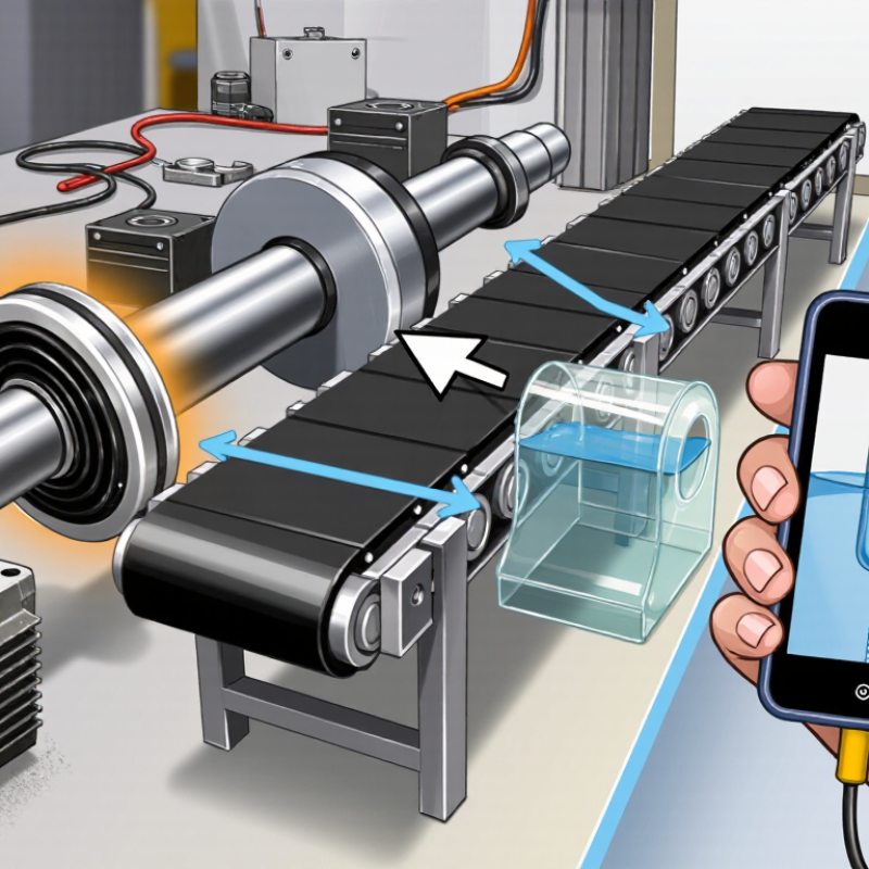
Choosing the right Velocity Sensor starts with the motion you need to measure, not the most impressive number on a datasheet. Is the target a rotating shaft, a moving belt, or fluid passing through a pipe? Each presents different challenges. A glossy encoder disk, a vibrating motor housing, and a clear water line demand different sensing methods.
Measurement authority Lord Kelvin offered a principle that still applies: “When you can measure what you are speaking about, and express it in numbers, you know something about it.” Kelvin was not a velocity-sensor specialist, but his point is useful: define the quantity before choosing the instrument. Decide whether you need linear or angular velocity, the expected range, required accuracy, response time, and operating conditions. Dust, vibration, temperature changes, and limited mounting space can matter as much as resolution. Small details count.
A sensor that performs well in a laboratory may struggle beside a hot motor or on a wet production line. Check the output type, installation requirements, calibration process, and compatibility with your controller. Then compare the total cost of ownership, including maintenance and replacement. There is no perfect sensor for every job. Even a careful selection can miss something; a short field trial often reveals what a specification sheet cannot. The right choice is the one that produces dependable readings in your actual setup, consistently and safely.
Define the Measurement Goal: Vibration Velocity Is Commonly Reported in mm/s RMS
Define the measurement goal before selecting a velocity sensor. For many rotating machines, vibration velocity is reported in millimetres per second RMS. RMS expresses the effective vibration level over a measurement period, rather than the highest instantaneous peak. It is useful for assessing overall vibration severity, but it can conceal a brief impact or a narrow resonance. That distinction matters. A bearing defect may produce sharp high-frequency events that an overall velocity value barely reflects.
Use a standard that fits the machine. ISO 20816-1:2016 provides general guidance for evaluating machine vibration, while ISO 20816-3:2022 covers specified industrial machinery rated above 15 kW and operating from 120 to 30,000 r/min. Those scope limits are not universal alarm thresholds. Evaluation zones depend on machine type, support, and operating conditions. Record the sensor location, mounting method, speed, and load so later readings are comparable. A handheld reading on a cool, lightly loaded pump may not match one taken under steady production.
For a stable trend, choose a sensor and measurement setup that capture the relevant frequency range and report RMS in mm/s. Check whether the instrument displays overall velocity or a filtered band; the numbers can differ. I would not trust one reading alone. ISO guidance supports structured evaluation, but it cannot replace knowing what the machine normally sounds and feels like.
Set the Required Bandwidth: ISO 2954 Covers 10–1,000 Hz
When choosing a velocity sensor, match its usable frequency range to the vibration you need to measure. ISO 2954 covers vibration-severity measurements from 10 to 1,000 Hz. It is a useful reference, but it does not mean every sensor performs equally well across that entire range. Check the sensor’s frequency-response data, and consider the full measurement chain, including mounting and signal conditioning.
The lower limit matters. Below 10 Hz, a measurement may not represent the range addressed by ISO 2954. At the upper end, sensor resonance or a declining response can distort readings. A motor running near 1,500 rpm produces vibration around 25 Hz, while some bearing-related signals occur much higher. The right bandwidth depends on the machine and the question being asked. Check the equipment’s operating speed and likely fault frequencies before choosing.
Fit matters too. A loose stud, uneven surface, or soft mounting pad can change the measured response. Keep the sensor firmly attached and use the same mounting method when comparing readings. Not every reading is trustworthy. It is tempting to treat a broad bandwidth as a guarantee, but calibration, mounting, and measurement conditions still matter. ISO 2954 provides a useful range; verify that your complete setup can measure it reliably.
How to Choose the Right Velocity Sensor
Set the Required Bandwidth: ISO 2954 Covers 10–1,000 Hz
Check that the sensor’s usable frequency response covers the vibration frequencies you need to measure. The range shown is 10–1,000 Hz; confirm the applicable requirements for your measurement and instrument.
Match Sensor Type and Sensitivity to the Expected Velocity Range
How to Choose the Right Velocity Sensor
Match Sensor Type and Sensitivity to the Expected Velocity Range
Start with the machine’s likely vibration velocity, not the sensor’s headline sensitivity. ISO 20816-3:2022 evaluates machine vibration using RMS velocity, reported in mm/s, with assessment zones that depend on machine type and installation. That makes the operating context essential: a pump on a rigid base may need a different measurement range from a flexible-mounted fan. Check expected minimum and maximum velocity, frequency range, and whether readings are RMS or peak.
For steady, lower-frequency vibration, an electrodynamic velocity sensor can provide a direct velocity output. A piezoelectric accelerometer with signal integration offers flexibility across a wider frequency range, but integration noise can affect readings near the low-frequency limit. Choose sensitivity so normal readings use a useful part of the acquisition system’s input range, while startup shocks do not cause clipping. For example, confirm the sensor’s mV/(mm/s) rating against the logger’s voltage range and resolution. A mismatch can hide small changes—or saturate the signal.
Tips: Check the sensor’s frequency response and overload limit, then compare them with the machine’s operating data. ISO 20816-3:2022 is a useful reference, but its criteria are not universal pass/fail limits. I’d verify mounting and cable routing, too; these details are easy to overlook.
Check Mounting, Temperature, and Output Compatibility Before Installation
How to Choose the Right Velocity Sensor
Check the machine’s mounting surface, operating temperature, and signal input before ordering a velocity sensor. A flat, rigid mounting point helps the sensor follow vibration instead of the housing’s local flex. ISO 5348 explains that accelerometer mounting affects frequency response; the same practical caution applies when evaluating vibration-sensor installations. A rushed choice can look fine on paper. It may not behave that way on a hot, vibrating motor.
Temperature ratings should cover both ambient air and the machine surface, including start-up heat. Then confirm the output type, sensitivity, and measurement units match the monitor or control system. A sensor can produce a clean signal that the receiving input cannot interpret correctly. The U.S. Department of Energy’s Operations & Maintenance Best Practices Guide reports predictive-maintenance savings of 8–12% over preventive maintenance. That benefit depends on usable measurements, not just installed hardware.
Tips: Check whether the input expects RMS or peak values, and verify the cable and connector fit the installation. For stud mounting, clean the contact surface and tighten to the specified torque. Adhesive mounting may be easier, but it can alter response. Recheck readings after installation; this small step is easy to miss.
Validate Readings Against the Applicable ISO 20816 Machine Criteria
How to Choose the Right Velocity Sensor
Validate Readings Against the Applicable ISO 20816 Machine Criteria
Choosing a velocity sensor is only part of a reliable vibration check. ISO 20816 does not provide one universal limit for every machine. The applicable part and machine classification matter, as do support conditions, measurement locations, and operating state. Check whether the criterion specifies vibration velocity RMS and a particular frequency range. Comparing peak or unfiltered data with an RMS limit can produce a misleading result. Small details matter.
Tips: Confirm the machine category before setting alarm limits. Use the prescribed measurement point, such as a bearing housing, and document sensor orientation. Check calibration, mounting rigidity, and frequency response. A loose magnetic base on a painted surface can alter readings.
A common weak point is treating a single reading as a verdict. Compare measurements taken under similar load and speed conditions, then look for repeatable changes. If readings sit near a boundary, verify the setup and consult the relevant ISO 20816 part rather than assuming the sensor is wrong. Keep the raw data and note any unusual operating conditions. The criteria guide assessment; they do not replace engineering judgment.